![]()
Hitrol
HRM-Series
Manual
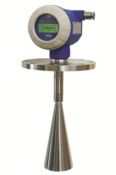
INTRODUCTION
HRM Series of FMCW method in the industry is the high level of non-contact level transmitter.
The environmental factors in non-contact level meter on the river is easy to install and high accuracy.
PRINCIPLE
FMCW(Frequency Modulated Continuous Wave) Radar(Microwave Type) Level Meter send Microwave Signal that be changed periodically to the surface of the objects to be measured. Then calculate the difference in frequency of the received signal. Because the received signal is proportional to the propagation distance, it is converted into distance to water by obtaining Δf.
FEATURES
● Liquid & powder
● Sequence measurements
● Spurious Rejection
● High temperature and pressure tank installation
● GUI PC Interface
● Variety of industrial installations
APPLICATIONS
● Nuclear power plant
● Thermoelectric power plant
● Hydroelectric power plant
● Filtration plant
● Sewage disposal plant
● Refined oil
● Petrochemical
● Ironworks/a refinery
● River/Dam
TECHNICAL SPECIFICATIONS
● Mounting method : Flange(Top) , Wall
● Temperature : Std.—- 80℃
Max.—- 200℃
● Working Pressure : Up to 30kg/cm2
● Enclosure : Weather-Proof(IP 65)
● Cable entry : PF PF 1/2″(F)
● Material Housing : AL.C
Process connection : SUS 304 / SUS 316
Antenna : SUS 304
ELECTRICAL SPECIFICATIONS
● Ambient Temp. : -20~+60℃
● Power source : AC 110/220V 60Hz
● Output signal : DC 4~20mA
● Power consumption : 4W
● Switch type : Relay
● Contact rating : AC 220V 3A
● Contact form : DPDT
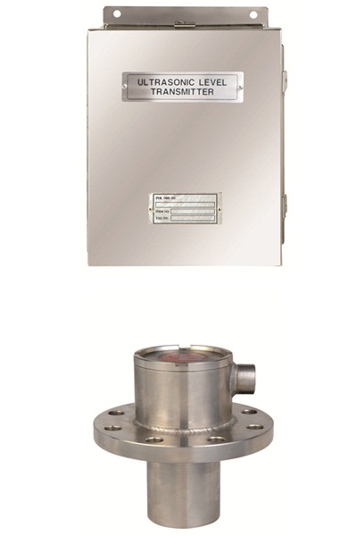
HUL/HUT-2000N
HUL_M_Kor.
Ultrasonic level meter mounted top of the tank and emit ultrasound pulse to measuring medium. Ultrasound pulse reach to the surface of measuring medium and reflected sound return back to sensor.
Ultrasound pulse reach to the surface of measuring medium and reflected sound return back to sensor.
These travel time calculated and converted to the reading level unit.
● ASF (abnormal signal filter) built-in
● Constraints minimize installation BEAM narrow angle (4 deg.)
● To monitor trends in data storage and data of 10,000 POINT
● Quality rating “Q” of the nuclear power plant, the world’s first
● Guarantee a durable design for nuclear power plants
● Seismic qualification,environmental qualification EMI/RFI,SOFTWARE V&V certified(shinkori NPP #3,4 CLASS-1E)
● Specific gravity, viscosity or temperature changes can be measured regardless of
● Nuclear
● Sensor/Transmitter : HUL-2000N / HUT-2000N
● Installation method : Flange / Wall
● Process connection : 4″ ANSI 150#(min.) / Bolt Mount
● Working temparature : Max.50℃
● Working Pressure : ATM
● Protection grade : Sensor — IP68, Transmitter — IP65
● Wire service entrance standard : NPT 3/4″
● Material : Sensor — 304 SS
Transmitter —- 304 SS
● Ambient temperature : -20℃ ~ +60℃
● Power : AC 90 to 240V, 50/60Hz
● Output : DC 4 to 20mA
● Contact : 8-SPDT/4-DPDT
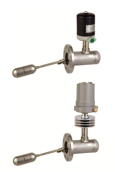
HM-90S Series
HM-90S_C_Eng.
HM-90S_C_Kor.
HM90S-Ex_M_Kor.
Model HM-90S is side mounting controls mount horizontally to any tank or vessel through a threaded or flanged pipe connection. Standard models are normally equipped with a single switch mechanism for high or low level alarm or control applications. Tandem models, when two level stage applications. Tandem models, when two switch mechanisms, are available for two level stage applications providing the operating functions of two separate instruments, such as high and low level alarm.
Side mounting units employ permanent magnetic force as the only link between the float and the switching element. As the pivoted float follows liquid level changes, it moves a magnetic sleeve into or out of the field of a switch operation. A non magnetic barrier tube effectively isolates the switch mechanism from the controlled liquid.
● different types of liquid level can be detected.
● robust structure and long life.
● High-temperature, High-pressure vessel can be used for.
● Check the operation status on site is available.
● Installation method is very convenient.
● Explosion-proof type can be manufactured.
● Boiler feeding drum water control
● Fuel oil tank level control
● Process control for petrochemical plants
● Nuclear power plant process control
● Other liquid level control
● Mounting Method : Side Flange
● Mounting Size : 65A JIS 10K RF
● Process Temp. : Std.—- 120℃
Max.—- 500℃(Ex Version 350℃)
● Working Pressure : Std.—- 10 kgf/cm2
Max.—- 63kgf/cm2
Ex-Proof(Ex d IIC T4, IP 65)
● Conduit Conn. : 2-PF 3/4″(F)
● Material Housing : C.S + AL.C, AL.C
Process connection : SUS 304
Float : SUS 304
● Ambient temperature : -20~+80℃
● Type of switch : Micro Switch
● Contact rating : AC 250V 15A, DC 125V 0.5A
AC 250V 5A, DC 125V 0.5A
AC 250V 1A, DC 125V 0.4A
● Contact form : SPDT, DPDT
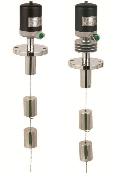
HM-30, HM-90 Series
HM90(B)_C_Kor.
HM90-Ex_M_Eng.
HM90-Ex_M_Kor.
Widely applicable level switch anti-flow of various liquid tank. model HM-90/30 is designed for liquid level control based on the unique and proven princijple of a constantly engaged magnetic field.
The sensor is a weight(displacer) heavier than the liquid, when is suspended by a spring. As liquid level changes the buoyant force generated causes the spring to react (compress or expand) to weight change. When the spring react, core moves by the rod and displacement movement is reflected in magnet and fixed magnet to pivot, on or off, according to the inner rod and core position. This principle allows adjustment of the swiching point by moving the displacer along the suspension cable.
Advantages of displacer controls ard that wide switching differentials can be achieved and higher operating pressure handled where traditional float operated units could not.
● Water treatment plants
● Mounting Method : Top Flange
● Mounting Size : 80A JIS 10K RF
● Process Temp. : Std. 120℃
Max. 500℃(Ex Version 350℃)
● Working Pressure : Std. 10 kgf/cm2
Max. 63kgf/cm2
Flaot : SUS 304
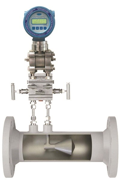
HFV-Series
HFV_M_Eng.
HFV_C_Eng.
HFV consists of a V-shaped cone element placed at the center of the pipe, leaving an annular space for the passage of fluid. The differential pressure generated by this device is lower than that of an orifice flowmeter with the same line size, beta ratio, and flow rate; hence, the permenent pressure loss is also lower.
Difference pressure occur between two measurement locations of the flowmeter because flow cross section that can be decribed as a restriction placed in the flow line.
We are able to know a flowrate that calculated by Bernouli’s equation from a differencial pressure.
● Required shorter straight lengths (Upstream : 5D, Downstream : 3D)
● High accuracy and reproducibility
● Widely Measurement Range
● Long life time because of no mechanical part
● PED CERTIFICATED (ASME B31.3 & ASME B31.1)
● Tested all flowmeter by certified test system (accordance to ISO 17025)
● Able to dual tap
● Water and Sewage treatment plant
● A hydro-electric power plant, A thermal power plant & Cogeneration plant
● Petrochemistry plant
● An iron mill
● Ocean plant (FPSO)
● Method of Installation : Flanged, Threaded, Welded End
● Operating Temperature : In accordance with material
● Operating Pressure : In accordance with material
● Accuracy : ±0.5 % F.S
● Measure Object : Liquid, Gas & Steam
● Size : 0.5″(15A) to 40″(1000A) or Larger
● Material : Body — Stainless Steel, Carbon Steel Other as required
Element — Stainless Steel Other as required
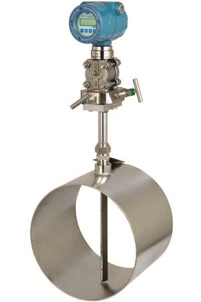
HAPT-Series
HAPT_C_Eng.
HAPT_M_Eng.
HAPT_M_Kor.
HAPT-Series is averaging pitot tube for flow measurement. Pitot tubes are normally used to measure flow velocities at a point. However, averaging pitot tubes are advantageous in that they can measure the average flow velocity in the entire pipe line to be measured instead of obtaining the flow velocity at a point. HAPT-Series have advantages such as lower pressure loss, longer life because of no moving parts and the structure which is difficult to sediment foreign substances.
When HAPT-Series are installed in pipe channels through which fluids flow, the differential pressure is generated when a fluid passes the element between the upstream and the downstream of the element. At this time, pressure difference, ie, dynamic pressure is obtained by measuring the total pressure of upstream and static pressure of downstream. Then, the flow rates of fluid can be obtained by using relations among the dynamic pressure, flow velocity and density derived from the Bernoulli’s law.
● High accuracy and repeatability
● Wide flow range
● Longer life(No moving parts)
● Structure which is difficult to sediment foreign substances.
● Lower pressure loss.
● Excellent durability
● Shipment after calibration and test
● AIR & GAS
● STEAM
● Waterworks
● Wastewater treatment
● Hydro, Thermal and Combined heat and power plants
● Ironworks
● Plant
● Mounting Method : Flange end, Weld end, Other as Required
● Accuracy : -/+ 1.0% F.S
● Temperature : Depend on material
● Pressure : From full vacuum to limits of Materials
● Line Size : 2in to 80in or larger
● Material : Element — 304SS or 316SS, C.S, Other as Required
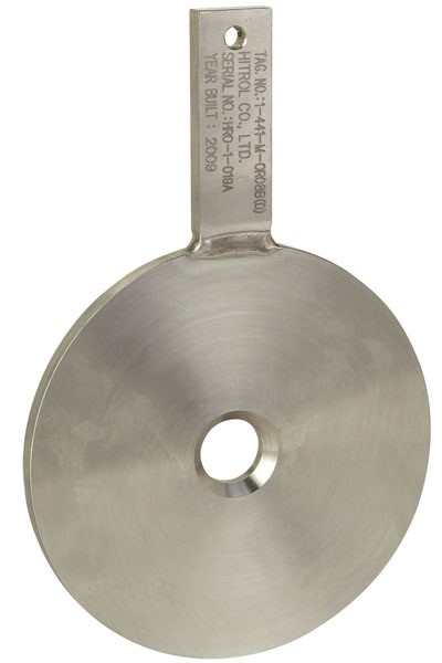
HOP-Series
HOP,HOF_M_Kor.
ORIFICE_C_Eng.
HOP-Series is orifice plate for flow measurement. Although the orifice plates have a disadvantage of permitting a greater pressure loss than other differential pressure type flow elements like as flow nozzle, venturi tube, etc. the flow measuring using the orifice plates most popularly used because of their simpler shape, easier manufacture ability, lower cost and higher reliability.
The bore types of orifice plates include concentric, eccentric, segmental, quarter circle, square bore type and sizing calculations apply the standard codes which are ISO-5167, ASME MFC-3M etc. and Tolerance should be in full compliance with ISO & ASME Standards.
When HOP-Series is installed in pipe channels through which fluids flow, the differential pressure is generated when a fluid passes the throat of an orifice because the flow speed increases and the pressure decreases to make pressure differences between the upstream and the downstream of the throat of the orifice. Then, the flow rates of fluid can be obtained by using the Bernoulli’s law with measured differential pressure.
● ISO 5167 and ASME MFC-3M design and fabrication
● Lower cost
● Simpler shape and easier to manufacture
● higher reliability
● CLEAR LIQUID
● Mounting method : Flanged, Other as required
● Accuracy : -/+ 2.0% F.S
● Temperature : Depends of material
● Pressure : Per ANSI B16.5
● Line size : 0.5in to 36in or larger
● Material : Element — 304SS or 316SS, Other as Required