
WAIRCOM MBS group was created in 1993 and within the span of twenty years, has consolidated its structure, by increasing its product line and by widening its sales network, and it has thus succeeded in becoming prominent as one of today’s Italian leading companies specializing in the manufacture of pneumatic components for automation. Currently WAIRCOM MBS is able to penetrate the market place thanks to the following features: a total floor area of 15.000 sqm comprising plants and offices, 3 production units conveniently located in Milan hinterland, concessionaries and resellers on the national territory, and a constantly growing export sales network. WAIRCOM MBS commercial and administrative headquarters are located in Vizzolo Predabissi industrial area, only 15 kilometres far from Milan where WAIRCOM MBS staff, consisting of approximately 100 employers, is taking advantage of experts that includes technicians, assembly personnel and office staff; everyone, and each for his own responsibility, is focused to the complete customer satisfaction. This is in fact the mission of our company: to preserve our customers through the complete satisfaction of their specific requirements, having in our mind only to pursue the continuous improvement in the fields of productive efficiency and costs. As natural result of such policy, WAIRCOM MBS Quality Management System has been found to be in compliance with the requirements as provided in the UNI EN ISO 9001 standard (see copy of the Quality Management System Certificate on the left).
Waircom offers an extensive range of cylinders that can satisfy the most disparate demands and industrial applications. We are able to propose linear (with or without piston rod), guided, compact, non-rotating and rotary actuators, that comply with the most common international standards or with our own designs and that point at the optimisation of the quality/price rate, without neglecting the always present care to the continuous innovation. All the series foresee, when not already included in the initial designs of the cylinders, even the application of convenient accessories or magnetic sensors that allow an even wider possibility of exploitation. As usual all these can work thanks to a production driven by a management of the quality system that complies all the demands included in the reference standard UNI EN ISO 9001:2000
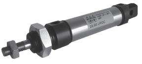
Stainless steel round cylinders with techno-polymer end caps (to ISO 6432 standard for Ø 16 ÷ 25)
DESCRIPTION
Cylinders series “UP” are born as technological efficient reply to the always new needs of different industrial fields. They are available from Ø 16 to Ø 50 among which Ø 16 ÷ 25 comply with ISO 6432 standard. These actuators set themselves as a valid yet economic alternative to cylinders completely made in stainless steel, in many “special” applications (as for example food, chemical and pharmaceutical industry…) and/or aggressive environments. In fact, the peculiar feature of this series is represented by the material used for the realization of the end caps: it’s a special techno-polymer that assures adequate mechanical properties.
TECHNICAL DATA
Operating pressure 1÷10 bar
Working temperature
0 ÷ +70 °C (- 20 °C with dry air)
Fluid Filtered, unlubricated or continuous lubricated compressed air
Versions Double acting, Single acting front spring, Single acting rear spring, through rod
Bore Ø 16, 20, 25, 32, 40, 50
Port size
Ø 16 = M5
Ø 20 ÷ 32 = G1/8
Ø 40 – 50 = G1/4
Standard strokes (mm) 10, 25, 50, 75, 80, 100, 125, 150, 160, 175, 200, 250, 300, 350, 400, 450, 500
Max strokes (mm)
Ø 16 = 250
Ø 20 ÷ 50 = 1000
Max strokes single act. (mm) Ø 16 ÷ 50 = 50
MATERIALS
End caps
Techno-polymer
Cylinder barrel Extruded tube, AISI 304 stainless steel
Barrel-end cover fixing type Irreversible calking with dual-seal system, mechanical and pneumatic
Piston rod
AISI 303 rolled stainless steel
Rod, end cap and ring nuts
Stainless steel
Piston Alluminium alloy with acetal resin piston bearing (supplied with and without magnet)
Seals Polyurethane
Springs Steel for springs
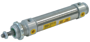
Round cylinders
DESCRIPTION
Cylinders series “P” are produced with a round profile design from Ø 32 to Ø 63. They are available in the basic version, with rear axial feed, with adjustable cushions and fitted for the use with magnetic sensors.
TECHNICAL DATA
Operating pressure 1÷10 bar
Working temperature
0 ÷ +80 °C (-20 °C with dry air)
0 ÷ +150 °C with seals for high temperature
(-10 °C with dry air)
Fluid Filtered, unlubricated or continuous lubricated compressed air
Versions Double acting; Single acting front spring; Single acting rear spring; Through rod; Flat rear cap (rear axial feed); Reduced flat rear cap
Bore Ø 32, 40, 50, 63
Port size
Ø 32 = G 1/8
Ø 40 – 50 = G 1/4
Ø 63 = G 3/8
Standard strokes (mm) 10, 25, 50, 75, 80, 100, 125, 150, 160, 175, 200, 250, 300, 320, 350, 400, 450, 500
Decelerators lenght
Ø 32 40 50 63mm 29 35 40 40
Max strokes (mm) Ø 32 ÷ 63 = 1000
Max strokes single act. (mm) Ø 32 ÷ 63 = 50
MATERIALS
End caps
Anodized alluminium alloy
Cylinder barrel Extruded tube, AISI 304 stainless steel
Barrel-end cover fixing type
Irreversible calking with dual-seal system, mechanical and pneumatic
Piston rod
C45 chromium-plated steel
AISI 303 rolled stainles steel
Rod nut and ring nut
Steel
Stainless steel (supplied upon request for the ring nut)
Decelerator ogives Anodized alluminium alloy
Piston rod bearing Self lubricating sintered bronze
Piston Alluminium alloy with acetal resin piston bearing (supplied with and without magnet)
Piston seals
Polyurethane – Viton®
Springs Spring steel
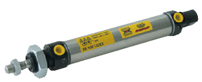
Cylinders to ISO 6432 standard
DESCRIPTION
Cylinders series “U” comply with ISO 6432 standard. The basic version is available for every diameter, while the rear axial feed, the magnetic piston and the adjustable cushions versions are produced from Ø 16 to Ø 25.
TECHNICAL DATA
Operating pressure 1÷10 bar
Working temperature
0 ÷ +80 °C ith dry air)
0 ÷ +150 °C with seals for high temperatures
(-10 °C with dry air)
Fluid Filtered, unlubricated or continuous lubricated compressed air
Versions Double acting; Single acting front spring; Single acting rear spring; Through rod; Flat rear cap (rear axial feed).
Bore Ø 8, 10, 12, 16, 20, 25
Port size
Ø 8 ÷ 16 = M5
Ø 20 – 25 = G1/8
Standard strokes (mm) 10, 15, 20, 25, 30, 40, 50, 60, 70, 80, 90, 100, 120, 125, 140, 150, 160, 180, 200, 250, 300, 350, 400, 500
Decelerators length
Ø 16 20 25
mm 17 18 18.5
Maximum strokes (mm) Ø 8 – 10 = 150; Ø 12 – 16 = 250; Ø 20 – 25 = 1000
Max. strokes single acting (mm) Ø 8 ÷ 12 = 20; Ø 16 ÷ 25 = 50
MATERIALS
End caps Anodized aluminium alloy
Cylinder barrel Extruded tube, AISI 304 stainless steel
Barrel-end cover fixing type Irreversible calking with dual-seal system, mechanical and pneumatic
Piston rod AISI 303 rolled stainless steel
Rod and end cap nuts Steel Stainless steel (supplied upon request)
Decelerators ogives Brass
Piston rod bearing Self-lubricating sintered bronze
Piston
Aluminium alloy with acetal resin piston bearing (supplied with and without magnet)
Piston seals NBR rubber – Viton®
Springs Springs steel
Direct acting solenoid valves 10 mm
DESCRIPTION
The direct acting solenoid valves series “DM” are produced in the 3/2 N.C. pneumatic function with the interface to ISO 1 521 8 and in the 3/2 N.O. – 3/2 N.C. pneumatic functions with not standardized interface. These valves can be used with all the fluids that can match the constructive materials. The versions with nominal diameter of 1 .1 mm are equipped with “CRP” (Power Reduction Circuit, see documentation below).
TECHNICAL DATA
Interface
to ISO 15218 or not standardized
Nominal diameter
Ø 0.7 mm (standard coil)
Ø 1 .1 mm (coil with “CRP”)
Operating pressure
0÷7 bar
Flow rate 1 -2 at 6 bar Δp=1
14 Nl/min
24 Nl/min
Flow rate 2-3 at 6 bar Δp=1 22 Nl/min
30 Nl/min
Working temperature
-5 ÷ +50°C
Fluid Filtered, unlubricated or continuous lubricated compressed air and other compatibles fluids
Max. operating frequency
≤ 40 Hz
Coil Adjustable
Voltages
DC: 6 – 12 – 24 V
AC: 24 V
DC: 12 – 24 V
Power consumption 1.3 W
3.5 W – 0.9 W
Voltage tolerance
-5 ÷ +10%
Protection class
IP 51 – IP 65 (only versions with embedded cables)
Insulation class
F (155° C)
Duty cycle
ED 100%
Energized Solenoid with response time = 8 ms
De-energized Mechanical spring with response time = 10 ms
Electric connector
With 90° and in-line connectors : series CN
MATERIALS
Core Stainless steel
Body and manual override PA and POM
Springs Stainless steel
Seals NBR and FKM rubber
Direct acting solenoid valves side 15 mm
DESCRIPTION
The direct acting solenoid valves series “UM” are produced in the 3/2 and 2/2 N.C./N.O. pneumatic functions. They are used as power valves if mounted on single and multi-station base, or as control valves if mounted, in the 3/2 pneumatic function, on body valves series “MEV”, “MEK”, or “UK”. These valves can be used with all the fluids that can match the constructive materials. The multi-station bases support both the 3/2 N.O. than the 3/2 N.C. pneumatic functions.
TECHNICAL DATA
Nominal diameter
0.8 mm
1.1 mm (standard) 1.6 mm
Operating pressure
0 ÷ 10 bar N.C.
Not available for N.O
0 ÷10 bar N.C.
0 ÷ 7 bar N.O. 0 ÷ 7 bar N.C.0 ÷ 5 bar N.O.
Flow rate 1-2 at 6 bar ∆p=1 20 Nl/min 30 Nl/min 50 Nl/min
Flow rate 2-3 at 6 bar ∆p=1 30 Nl/min 30 Nl/min 50 Nl/min
Working temperature -5 ÷ +50 °C
Fluid Filtered, unlubricated or continuous lubricated compressed air and other compatibles fluids
Max. operating frequency ≤ 30 Hz
Coil Adjustable
Voltages DC: 24 V DC: 12 – 24 V
AC: 24 – 110 – 220 V
Power consumption DC: 1 W DC: 2.5 W
AC: 2.8 VA (inrush) – 2.5 VA (holding)
Voltage tolerance -5% ÷ +10%
Protection class IP 51 – IP 65 ( versions: with embedded cables or standard + connector MEK192/N )
Insulation class F (155°C)
Duty cycle Continuous rating (ED 100%)
Energized Solenoid with response time = 5 ms
De-energized Mechanical spring with response time = 6 ms
Electric connectors With faston: series MEK192/N – see chapter Connectors on page 7
With 90° and in-line connectors: series CN – see chapter Connectors on page 7
MATERIALS
Core Stainless steel
Body and manual override PA and POM
Springs Stainless steel
Seals NBR and FKM rubber
Direct acting solenoid valves side 32 mm
DESCRIPTION
The direct acting solenoid valves series “UL” are produced in conformity with the Directives EC 89/336, EC 92/31, EC 93/68, EC 73/23 in the 3/2 N.O. (with feed from the exhaust “3”) and 3/2 N.C. pneumatic functions. The function 2/2 is obtainable closing exhaust “3”. Besides are available the versions with ports G 1/8, suitable for single use, and with interface for multi-station base mounting or for mounting on poppet and to ex CETOP RP 32 P (with fixed position) valve bodies.
TECHNICAL DATA
Operating pressure
N.C. = 0 ÷10 bar
N.O. = 0 ÷ 6 bar
Working temperature
0 ÷ +50 °C (-20 °C with dry air)
Fluid
Filtered, unlubricated or continuous lubricated compressed air
Nominal diameter
2 mm
Max.operating frequency
≤13 Hz
Coil
Intergrated in the body
Voltages
DC: 24 V
AC: 24 – 110 – 220 V
Apparent power
DC: 7 W
AC: 17 VA (inrush) – 10 VA (holding)
Voltage tolerance
-15% +15%
Protection class
IP 65
Insulation class
F
Solenoid rating ED 100%
Electric connector
ULR1B – see chapter Connectors on page 2.15
MATERIALS
Core IMRE
Body ported G 1/8 Zamak
Body with interface Glass stiffened polyamide (zamak upon request)
Springs Stainless steel
Seals Viton®
Manual override Acetal resin