[et_pb_section admin_label=”Section” fullwidth=”off” specialty=”off”][et_pb_row admin_label=”Row”][et_pb_column type=”1_3″][et_pb_sidebar admin_label=”Sidebar” orientation=”left” area=”sidebar-1″ background_layout=”light” remove_border=”off”]
[/et_pb_sidebar][/et_pb_column][et_pb_column type=”2_3″][et_pb_text admin_label=”Text” background_layout=”light” text_orientation=”justified” use_border_color=”off” border_color=”#ffffff” border_style=”solid”]
OUR PLC Partners
What is a PLC (Programmable Logic Controller)
300-115 CiscoExam EX200350-018 Exam200-120 CiscoCompTIA SY0-401N10-006 Network+400-101 CCIEExam 300-101MB6-703 MSS70-488 ExamCisco 350-018070-462 ExamSY0-401 CompTIAPMI PMPCAS-002 CASP350-018 ExamCCDA 200-310PMP PMICCNP Security 300-20670-980 MCSE400-101 ExamSalesforce ADM-2011Z0-060 OracleN10-006 CompTIACCENT/CCNA ICND1 100-101300-208 SISAS810-403 CiscoMSS: Dynamics CRM 2013 MB2-7041Z0-061 Oracle642-999 CiscoExam 70-980100-101 ExamSY0-401 Security+Cisco 200-310300-206 ExamCISSP CISSPExam 300-1019L0-012 ACMTJava SE 8 Programmer 1z0-808ICBB ExamN10-006 CompTIAApple 9L0-012OG0-093 The Open GroupMB2-707 ExamExam 300-075350-018 ExamMB5-705 ExamExam 070-462MB6-703 MSSEX200 RedHatF5 101300-135 CCNP Routing and Switching
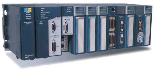
A Programmable Logic Controller, or PLC, is more or less a small computer with a built-in operating system (OS). This OS is highly specialized to handle incoming events in real time, i.e. at the time of their occurrence.
The PLC has input lines where sensors are connected to notify upon events (e.g. temperature above/below a certain level, liquid level reached, etc.), and output lines to signal any reaction to the incoming events (e.g. start an engine, open/close a valve, etc.).
The system is user programmable. It uses a language called “Relay Ladder” or RLL (Relay Ladder Logic). The name of this language implies that the control logic of the earlier days, which was built from relays, is being simulated.
The PLC’s purpose in life
The PLC is primarily used to control machinery. A program is written for the PLC which turns on and off outputs based on input conditions and the internal program. In this aspect, a PLC is similar to a computer. However, a PLC is designed to be programmed once, and run repeatedly as needed. In fact, a crafty programmer could use a PLC to control not only simple devices such as a garage door opener, but their whole house, including switching lights on and off at certain times, monitoring a custom built security system, etc.
Most commonly, a PLC is found inside of a machine in an industrial environment. A PLC can run an automatic machine for years with little human intervention. They are designed to withstand most harsh environments.
History of PLCs
When the first electronic machine controls were designed, they used relays to control the machine logic (i.e. press “Start” to start the machine and press “Stop” to stop the machine). A basic machine might need a wall covered in relays to control all of its functions. There are a few limitations to this type of control.
Relays fail.
The delay when the relay turns on/off.
There is an entire wall of relays to design/wire/troubleshoot.
A PLC overcomes these limitations, it is a machine controlled operation.
Recent developments
PLCs are becoming more and more intelligent. In recent years PLCs have been integrated into electrical communications(Computer network|networks)i.e., all the PLCs in an industrial environment have been plugged into a network which is usually hierarchically organized. The PLCs are then supervised by a control centre. There exist many proprietary types of networks. One type which is widely known is SCADA (Supervisory Control and Data Acquisition).
Basic Concepts
How the PLC operates
The PLC is a purpose-built machine control computer designed to read digital and analog inputs from various sensors, execute a user defined logic program, and write the resulting digital and analog output values to various output elements like hydraulic and pneumatic actuators, indication lamps, solenoid coils, etc.
Scan cycle
Exact details vary between manufacturers, but most PLCs follow a ‘scan-cycle’format.
Overhead
Overhead includes testing I/O module integrity, verifying the user program logic hasn’t changed, that the computer itself hasn’t locked up (via a watchdog timer), and any necessary communications. Communications may include traffic over the PLC programmer port, remote I/O racks, and other external devices such as HMIs (Human Machine Interfaces).
Input scan
A ‘snapshot’ of the digital and analog values present at the input cards is saved to an input memory table.
Logic execution
The user program is scanned element by element, then rung by rung until the end of the program, and resulting values written to an output memory table.
Output scan
Values from the resulting output memory table are written to the output modules.
Once the output scan is complete the process repeats itself until the PLC is powered down.
The time it takes to complete a scan cycle is, appropriately enough, the “scan cycle time”, and ranges from hundreds of milliseconds (on older PLCs, and/or PLCs with very complex programs) to only a few milliseconds on newer PLCs, and/or PLCs executing short, simple code.
Basic instructions
Be aware that specific nomenclature and operational details vary widely between PLC manufacturers, and often implementation details evolve from generation to generation.
Often the hardest part, especially for an inexperienced PLC programmer, is practicing the mental ju-jitsu necessary to keep the nomenclature straight from manufacturer to manufacturer.
Positive Logic (most PLCs follow this convention)
True = logic 1 = input energized.
False = logic 0 = input NOT energized.
Negative Logic
True = logic 0 = input NOT energized
False = logic 1 = input energized.
Normally Open
(XIC) – eXamine If Closed.
This instruction is true (logic 1) when the hardware input (or internal relay equivalent) is energized.
Normally Closed
(XIO) – eXamine If Open.
This instruction is true (logic 1) when the hardware input (or internal relay equivalent) is NOT energized.
Output Enable
(OTE) – OuTput Enable.
This instruction mimics the action of a conventional relay coil.
On Timer
(TON) – Timer ON.
Generally, ON timers begin timing when the input (enable) line goes true, and reset if the enable line goes false before setpoint has been reached. If enabled until setpoint is reached then the timer output goes true, and stays true until the input (enable) line goes false.
Off Timer
(TOF) – Timer OFF.
Generally, OFF timers begin timing on a true-to-false transition, and continue timing as long as the preceding logic remains false. When the accumulated time equals setpoint the TOF output goes on, and stays on until the rung goes true.
Retentive Timer
(RTO) – Retentive Timer On.
This type of timer does NOT reset the accumulated time when the input condition goes false.
Rather, it keeps the last accumulated time in memory, and (if/when the input goes true again) continues timing from that point. In the Allen-Bradley construction, this instruction goes true once setpoint (preset) time has been reached, and stays true until a RES (RESet) instruction is made true to clear it.
Latching Relays
(OTL) – OuTput Latch.
(OTU) – OuTput Unlatch.
Generally, the unlatch operator takes precedence. That is, if the unlatch instruction is true then the relay output is false even though the latch instruction may also be true. In Allen-Bradley ladder logic, latch and unlatch relays are separate operators.
However, other ladder dialects opt for a single operator modeled after RS (Reset-Set) flip-flop IC chip logic.
Jump to Subroutine
(JSR) – Jump to SubRoutine
For jumping from one rung to another the JSR (Jump to Subroutine) command is used.
PLC is a great invention in the industrial environment.
[/et_pb_text][/et_pb_column][/et_pb_row][/et_pb_section]